
1. What is a Contactor?
A contactor is an electrically controlled switch used for switching an electrical power circuit. It is used to control heavy electrical loads like motors, lighting, heating systems, and other high-power devices. Unlike manual switches, contactors operate automatically through electrical signals, making them safer and more efficient in industrial and commercial applications.
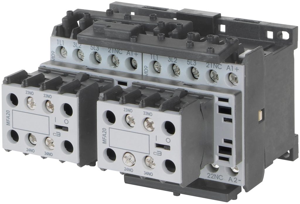
Main Components of a Contactor:
- Coil (Electromagnet): The coil is the heart of the contactor. When it is energized, it generates a magnetic field that pulls the contacts together.
- Contacts: These are the main current-carrying parts of a contactor. They consist of power contacts, auxiliary contacts, and contact springs. Power contacts control the main power supply to the load, while auxiliary contacts handle control circuits.
- Enclosure: This part protects the internal components of the contactor from dust, dirt, and mechanical damage. It is usually made of insulating materials.
Contactors are favored for their ability to control large currents with a small control signal, enhancing safety and providing reliable operation in high-demand electrical systems.
2. Different Types of Contactors
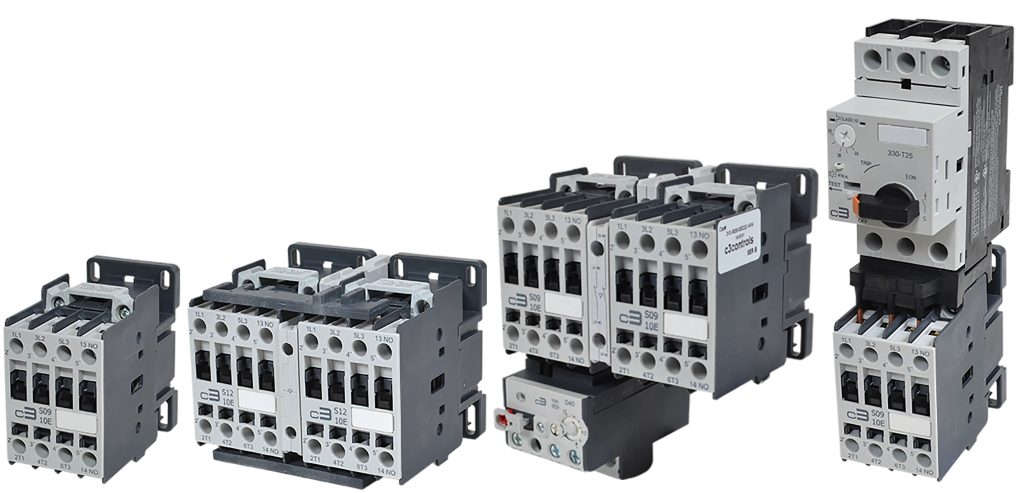
Contactors come in various types, each designed for specific applications and environments. Below are some of the most common types:
- Magnetic Contactors: These are the most common type and use an electromagnet to close the contacts. They are widely used in motor control and other applications where frequent switching is required. Magnetic contactors are known for their reliability and ease of use.
- Vacuum Contactors: Vacuum contactors operate using a vacuum as the arc-extinguishing medium. They are ideal for high-voltage applications, such as in power distribution systems, because they minimize contact wear and provide high-speed switching with minimal maintenance.
- Air-Break Contactors: These contactors extinguish the arc in an air environment when the contacts open. They are often used in industrial motor control applications and are relatively simple in construction but can be prone to contact erosion over time.
- Oil Contactors: Oil contactors use oil as an insulating medium to suppress the arc when the contacts open. They are used less frequently today due to environmental concerns and maintenance requirements but were popular in older high-power systems.
- Solid-State Contactors: These contactors use semiconductor devices (such as thyristors or triacs) instead of mechanical contacts to switch circuits. They provide silent operation, faster switching, and longer life due to the absence of moving parts, making them suitable for applications where noise and mechanical wear are concerns.
- Definite Purpose Contactors: These are designed for specific applications such as HVAC, refrigeration, or lighting. They are less expensive and have lower endurance compared to standard contactors, making them suitable for dedicated uses where high durability is not critical.
- Lighting Contactors: Designed specifically for controlling large lighting loads, these contactors handle the high inrush currents associated with turning on multiple lights simultaneously. They are used in commercial buildings, sports facilities, and other areas with large lighting systems.
- Capacitor Switching Contactors: Used primarily for switching capacitor banks in power factor correction applications, these contactors have special resistors to reduce inrush current and minimize the risk of contact damage.

3. How Does the Contactor Device Work?
The operation of a contactor is simple yet crucial for controlling electrical circuits. Here’s a detailed step-by-step explanation of how it works:
- Power to the Coil: When a control signal is sent to the contactor, it energizes the coil, creating a magnetic field. This control signal is usually a low voltage and low current input from a control switch or relay.
- Contact Movement: The magnetic field generated by the coil pulls the movable core, which in turn pulls the movable contacts toward the fixed contacts. This closes the circuit, allowing electricity to flow through the contactor to the connected load.
- Current Flow: With the contacts closed, electrical power flows from the power source, through the contactor, and to the connected equipment, such as a motor, lighting system, or heating element. The contactor effectively acts as a gate, controlling when power is supplied.
- Breaking the Circuit: When the control signal to the coil is removed, the magnetic field collapses, releasing the movable core. The contacts spring back to their original open position, breaking the circuit and stopping the power flow.
- Arc Suppression: During the opening of the contacts, an electrical arc can form, especially in high-power circuits. Contactors are designed with arc chutes, blowout coils, or other arc-suppressing features to safely extinguish this arc and protect the contacts from damage.
This straightforward but robust mechanism allows contactors to control high-power devices efficiently and safely, making them indispensable in electrical control systems.
4. Difference Between AC Contactor and DC Contactor
AC and DC contactors serve similar purposes but are optimized for their respective types of current. Understanding their differences helps in selecting the right one for the application.
- AC Contactors:
- Design: AC contactors are designed to handle alternating current (AC) loads. They have shading coils, which are small copper rings on the contactor’s core. Shading coils reduce noise and prevent the contacts from chattering when the current fluctuates at each AC cycle.
- Applications: AC contactors are commonly used in motor starters, HVAC systems, lighting controls, and other AC-powered devices.
- Arc Handling: AC contactors handle arcs better due to the natural zero-crossing of the current, which helps extinguish the arc more easily.
- DC Contactors:
- Design: DC contactors are optimized for direct current (DC) loads. They lack shading coils since DC does not cause the contact chattering associated with AC. However, DC currents create stronger, more persistent arcs when the circuit is broken.
- Applications: DC contactors are used in electric vehicles, battery systems, solar power setups, and other DC-powered equipment.
- Arc Suppression: DC contactors often include arc blowout magnets or other arc suppression methods to handle the stronger arcs generated by DC circuits.
Key Differences:
- Arc Suppression Needs: AC contactors use natural current zero crossings to suppress arcs, while DC contactors rely on special design features to handle persistent arcs.
- Application Suitability: Use AC contactors for AC loads and DC contactors for DC loads to ensure safety and performance.
5. Contactor vs. Relay
While contactors and relays both control electrical circuits, they differ significantly in terms of capacity, design, and use:
- Size and Load Capacity: Contactors are much larger and handle higher power loads compared to relays. Relays are typically used in control and automation circuits for switching smaller currents.
- Arc Management: Contactors have arc suppression features due to their use in high-power circuits. Relays, dealing with smaller loads, often do not require such complex arc management.
- Applications: Relays are suited for signal switching, automation, and low-current applications. Contactors are designed for controlling high-power devices like motors, heaters, and industrial machinery.
- Durability and Design: Contactors are built for frequent switching and long operational life under heavy loads. Relays are not as robust and are used where switching is less demanding.
Choosing Between a Contactor and a Relay:
- Use a relay when switching small control circuits or automation tasks.
- Use a contactor for handling large currents and high-power loads, ensuring safety and reliability in industrial settings.
6. Conclusion
Contactors are crucial components in electrical systems, allowing for the safe and efficient control of high-power devices. From magnetic to vacuum and solid-state types, each contactor serves a unique role tailored to specific applications. Understanding how they work and the differences between AC and DC contactors helps in selecting the right component for your needs.
Whether managing lighting systems, controlling motors, or switching high-current circuits, contactors provide a reliable solution that enhances operational safety and efficiency. While they share some similarities with relays, contactors are designed to handle much heavier loads, making them essential in industrial and commercial applications.
When choosing a contactor, consider the type of current, load requirements, and the environment in which it will operate. This knowledge ensures the right fit for your system, enhancing performance and longevity.